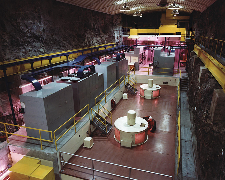
The permanent magnet generator manufacturer shortlist has three names and three matching kilowatt figures. That apparent match lasts one page. Supplier A stops at generator terminals. B adds a converter but leaves cooling and bearings open. C offers a package built around a prime-mover assumption that nobody has checked. Qualification starts when the boundary and the assumptions are pulled into the same room.
This is an illustrative review, not a ranking or order report. The names are absent on purpose. What matters is the request, the evidence, and one common comparison boundary.
The buyer starts with a duty sheet, not a shortlist
At the top of page one is the prime mover. Wind rotor? Water turbine? Engine, test rig, or something else? The answer changes the rest of the sheet. Minimum and maximum speed are plotted first. Normal points, torque or power, overspeed, direction, acceleration, and time at duty follow.
Electrical output comes next. AC or rectified DC? Which voltage window? Which frequency range matters before conversion? What converter or load will be connected? How will faults, braking, dumping, or grid loss be handled? A manufacturer cannot select winding and converter assumptions from the phrase “permanent magnet generator” alone.
A blank stays blank. Beside it go an owner's initials and a date. That is easier to close than a convenient number buried in the winding design.
The speed range exposes the proposed architecture
The first bidder proposes a higher-speed generator after a transmission. The second chooses a medium-speed arrangement. The third integrates a low-speed machine more directly with the prime mover. Each can be a real PMG architecture. Their bearings, structure, cooling, converter range, service access, and maintenance are not alike.
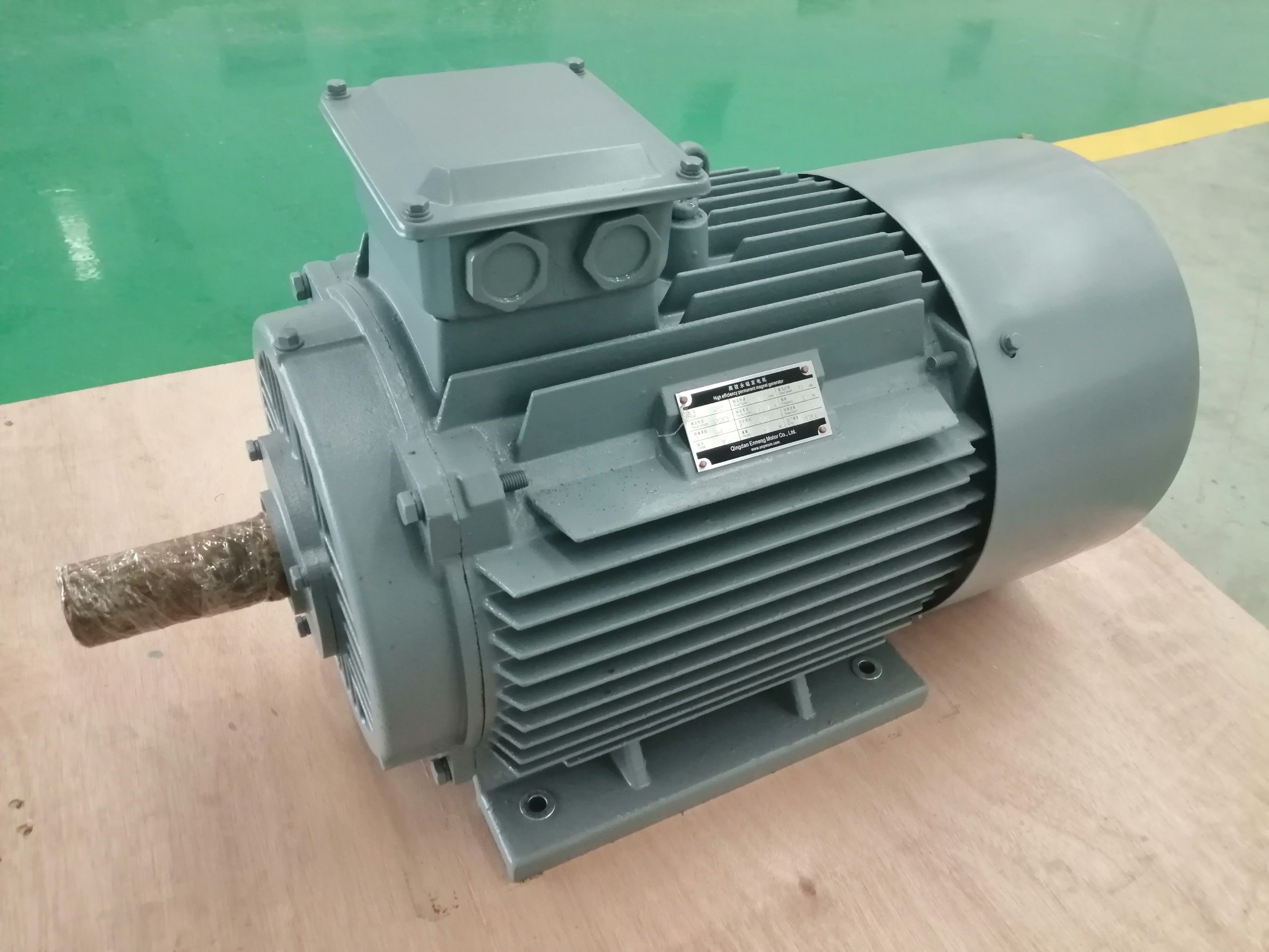
The team asks each manufacturer to draw the mechanical and electrical chain. Shafts, bearings, couplings, gearbox where present, generator, rectifier, DC link, converter, transformer where present, protection, and load are labeled. Removed components are crossed out. Customer-supplied items get a different color.
ABB's official permanent magnet generator overview describes high-speed, medium-speed, and direct-drive concepts within its own renewable-generator offering. The page supports the existence of those architectures. Its benefits and performance statements remain ABB product claims and are not transferred to ENNENG.
A credible proposal connects speed to electrical output
One sheet gives rated voltage at one speed. The reviewer draws a box around that single dot. What happens above it, below it, and under different load? Where does generator behavior end and electronic control begin? If the quote includes rectification, the DC window goes on that same sheet.
The converter engineer walks through events rather than labels: startup, normal load, open circuit, rejected load, fault, overspeed, and the dump or brake path. Then come cable length, insulation, ground, harmonics, filters, switching, and heat. Leaving the converter until later might send the winding and voltage window back to design.
On the PMG voltage regulation guide, the team separates raw machine output from what rectifiers and converters control. Quotations become less slippery once that line is drawn.
Mechanical interface evidence comes before manufacturing
The prime-mover drawing goes beside the generator outline. A pencil follows shaft and flange, then bolts, coupling, centerline, and orientation. Load arrows show radial force, thrust, and torque reaction; notes cover runout and alignment. One integrated concept pulls bearing duty into the generator. Another leaves thrust at the turbine.
Ownership is read aloud. Torsion? Critical speed? Overspeed integrity and balance? Bearing calculation, seals, lubrication, thermal growth? Some rows will be marked not applicable. None of the applicable rows may be ownerless.
At a retrofit site, the tape measure gets a vote. The team walks the lift and removal paths, checks service space and foundation, then marks cooler and cable connections. A neat envelope can still trap the generator behind nearby equipment.
Cooling is reviewed across the operating map
Losses move as speed, current, voltage, and converter state move. The cooling proposal therefore needs its duty beside it. Air cooling ends in one set of auxiliaries; separate ventilation in another; a water jacket brings a different site job again.
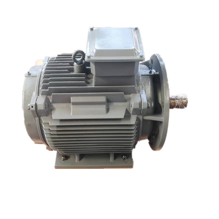
The location is written plainly first: hot, high, salty, dusty, wet, tilted, indoors or outdoors. Engineering values follow, along with the utilities actually available. Fans and filters go on the air quote. Pump, exchanger, hoses, and flow proof go on the water quote. Heaters, drains, and temperature signals stop hiding under “standard accessories.”
Someone covers the cooling-proof signal on the diagram. What happens next? The schedule may warn, reduce load, or stop, depending on the approved design. It also has to name the sensor, wire, setting, controller, and commissioning record.
Standards are named by part and edition
A bidder writes “IEC compliant.” The buyer adds three question marks: which document, part, and edition? The current IEC 60034 series does not collapse rating, losses, enclosure, cooling, mounting, vibration, and insulation into one promise. Its structure shows why the project must be specific.
The project identifies what applies to its generator and installation. Additional marine, hazardous-area, grid, utility, or customer standards may sit outside that series. A certificate is checked for issuing body, scope, model or process covered, validity, and whether it actually applies to the offered configuration.
“Designed to” and “certified to” are not treated as synonyms. The first may describe an engineering basis. The second requires the relevant controlled certificate or report.
Factory capability is checked with evidence
The brochure closes. The process map opens. Who controls the winding and magnet work? Where are rotor assembly, balance, insulation, and machining done? Which critical steps leave the building, and what control follows them?
Nobody insists that every operation live under one roof. The boundary simply has to be clear. Material record, inspection point, nonconformance, calibration, drawing revision, traveler, and final release each need a real control and an owner.
A factory photograph can show a machine. It can't show today's calibration or prove process capability. The qualification file therefore asks for order-relevant records instead of another gallery link.
Testing is written as a matrix
“Factory tested” is circled and unpacked. In the matrix, every row answers the same questions: what test, under which condition, using which calibrated instrument, after what wait, within what tolerance, in which report, witnessed and signed by whom? Routine checks and an unloaded run do not share a row with a thermal program.
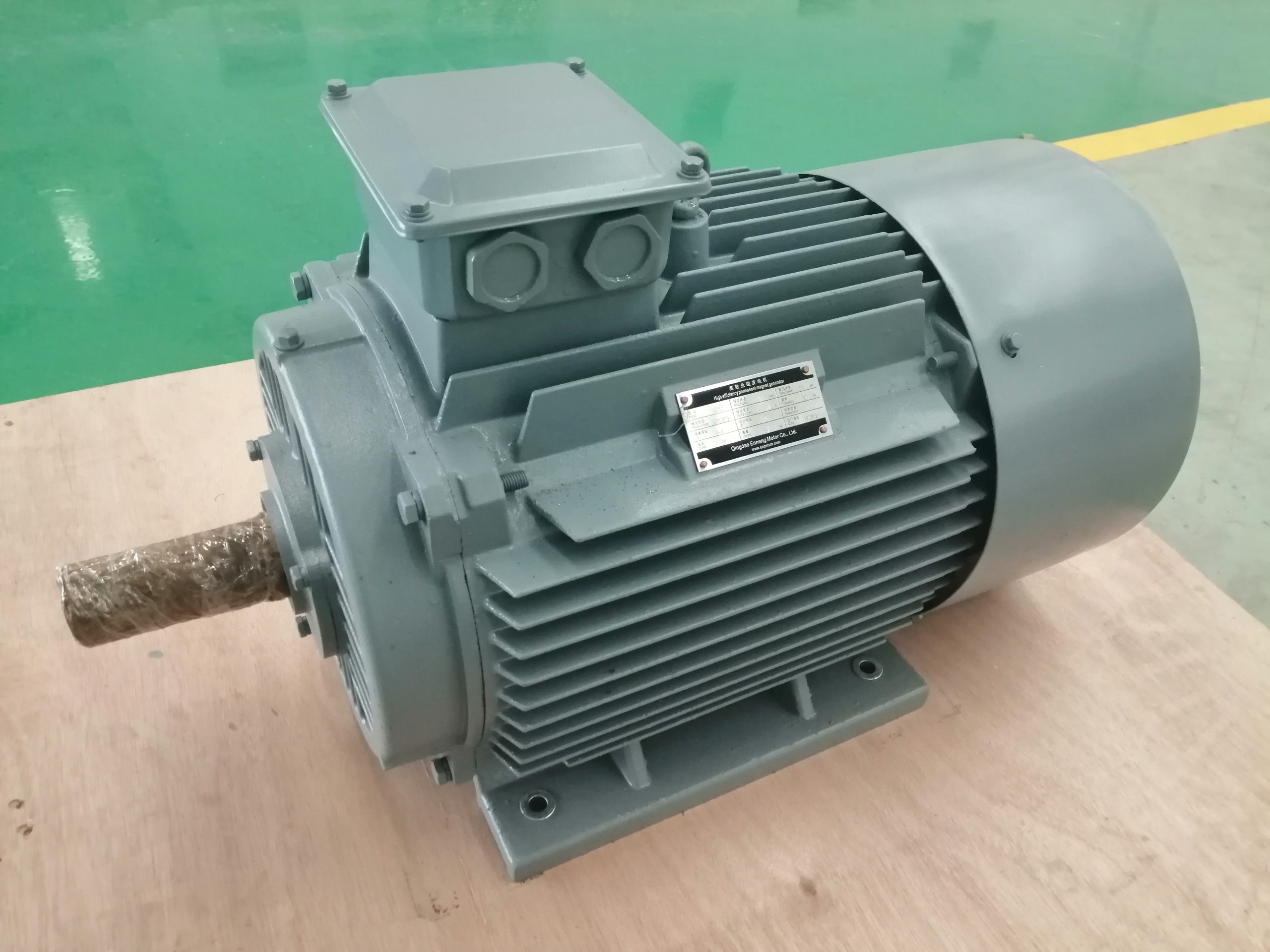
The factory cannot reproduce one full-duty corner. That gap remains visible. Calculation, component evidence, partial-load work, and site acceptance are stitched into one plan. Where risk and standard call for overspeed or fault evidence, those items are written separately.
Before anyone copies an efficiency figure into the business case, the permanent magnet generator efficiency guide makes them write the boundary, operating point, uncertainty, and converter loss beside it.
Documents reveal whether the supplier can finish the job
The installer runs a paper test. Can the machine be built and connected from the approved data sheet and curves? Are the outline, interfaces, shaft, bearings, terminals, sensors, and cooler clear? Do converter inputs, protection, tests, reports, manuals, required certificates, packing, and spares close the remaining folders?
The order puts language, format, status, review cycle, and due date beside each deliverable. “Preliminary” cannot quietly turn into “released for manufacture.” A manual arriving after startup has missed the person who needed it.
A late shaft change becomes the revision test. Did the winding data, sensor list, cooler drawing, and affected interface follow it? If not, the package has split into versions.
Commercial comparison follows the technical boundary
Three cost columns replace the headline total. Delivered equipment stops at the first. The project column follows engineering, tests, paperwork, packing, freight, field help, startup, and training. The operating column follows auxiliary power, care, spares, downtime assumptions, and replacement.
Currency, tax basis, Incoterm, payment milestones, validity, warranty, delivery trigger, drawing approval, manufacturing time, and transport are read together. A short lead time that starts after final drawing approval is not the same as a short lead time from purchase order.
Deviations stay in a log. Engineering decides whether they work. Procurement values them. The manufacturer confirms the accepted wording. Missing mandatory scope receives a realistic allowance rather than a zero.
The final qualification decision is conditional
Company qualification is one gate. Project approval is another. The first asks whether quality, engineering, manufacturing control, documentation, and support are credible. The second points at the offered generator and asks whether its converter boundary, mechanics, cooler, protection, and tests fit this duty.
The ENNENG evidence is narrow. ENNENG-CAND-007 records limited archived PMSG family context; ENNENG-CAND-010 records a customization statement. Neither proves certification, test capacity, fit, delivery, or performance for a new order. Review the generator product context, then send prime-mover and electrical data.
Evidence boundary
ABB supplies general architecture context for its cited products. IEC supplies the standards map, not a manufacturer certificate. The admitted ENNENG records support only the limited historical statements above. Current controlled evidence is still required for supplier qualification; the exact data sheet, drawings, quality plan, tests, and offer remain the project gate.