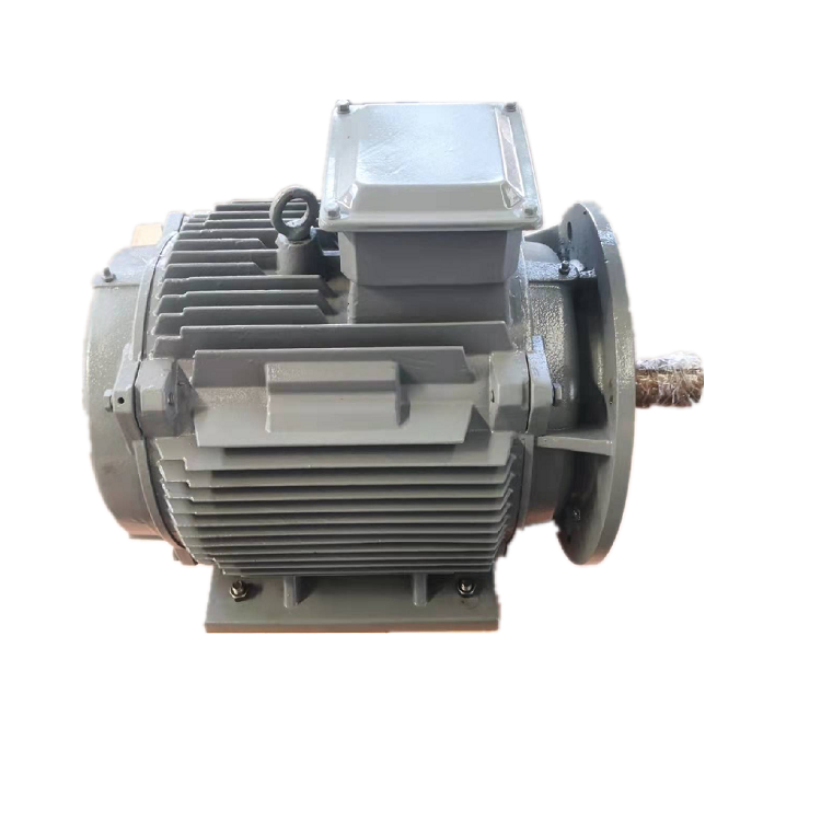
PMG voltage regulation is a system-design task because a permanent-magnet generator has no wound rotor field that a conventional automatic voltage regulator can adjust. Terminal voltage changes with speed, load, winding impedance, temperature, rectification, and converter control. Stable DC, fixed-frequency AC, battery charging, and grid export therefore require different architectures. This guide explains the questions an integrator should answer before selecting a PMG, rectifier, DC link, inverter, or protection scheme.
Define what “regulated voltage” means for the load
Begin at the receiving equipment. State whether it needs raw three-phase AC, rectified DC, a controlled battery-charging profile, an isolated DC bus, or grid-quality AC. Define nominal voltage, permissible steady-state band, ripple, transient deviation, recovery time, frequency, harmonics, and power factor as applicable. Add minimum and maximum load and any step changes. A phrase such as “400 V output” is incomplete without speed and load conditions.
Mark the measurement point. Generator terminal voltage, rectifier output, DC-link voltage, inverter output, and point-of-connection voltage are different quantities. Draw the complete path and assign responsibility for each stage. The PMG selection guide helps organize speed, power, voltage, environment, and mechanical data before these interfaces are fixed.
Relate generated voltage to speed and winding design
In a PMG, rotor magnets establish flux, and generated frequency follows mechanical speed and pole count. Generated voltage also varies with speed and is affected by load current and internal impedance. Winding turns and connection influence the voltage-current trade, but changing them is a machine-design decision with thermal, insulation, and converter consequences. A no-load voltage at one speed is not a regulation specification.
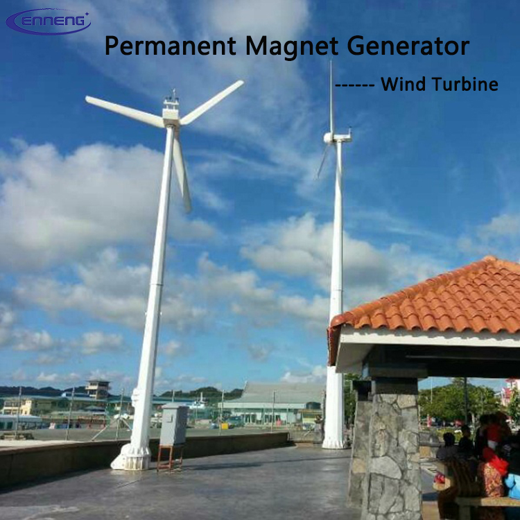
Provide minimum, normal, and maximum speed, including overspeed and coast-down. Add the torque or power available at each point. NREL's official wind turbine modeling report presents the basic relationship among synchronous-generator speed, electrical frequency, and pole count and explains that permanent-magnet generator control acts through armature current rather than field excitation. Use it for general principles; project values must come from the proposed generator data.
Distinguish passive rectification from active conversion
A diode bridge is simple and robust, but its DC output follows generator voltage and load, minus device drops and commutation effects. It cannot independently command generator current over a wide range. A downstream DC-DC converter can regulate a DC bus or charging current within its voltage and power limits. An active rectifier can control generator current and torque, but adds switching devices, controls, sensing, cooling, and protection.
Choose the topology from the required speed range, load, efficiency, fault response, and cost. NREL's WindPACT drivetrain study describes power-electronic systems for permanent-magnet synchronous generators, including full-rated conversion and different converter arrangements. The report shows why power electronics are part of the generator architecture. It does not make one topology universally best.
Size the DC link for normal and abnormal energy flow
Define the generator-side voltage range, rectifier output range, DC-link target, capacitance, ripple current, precharge, discharge, and overvoltage limit. Consider what happens during a sudden load rejection while the prime mover continues to supply torque. Energy can raise the DC-link voltage rapidly. The design may need converter control, a dump load, braking chopper, pitch or flow control, mechanical braking, or an orderly shutdown coordinated with the prime mover.
Also analyze low-speed start and weak-source behavior. A converter may need a minimum voltage before control becomes active. Auxiliary controls, contactors, and cooling may require an independent supply. Define black start, standby, and restart after a fault. If batteries are connected, include reverse-current blocking, charging limits, battery management, and fault isolation. These decisions cannot be deferred to generator commissioning.
Coordinate the generator, converter, and prime mover
Voltage regulation cannot be separated from torque control. When the converter increases generator current, electromagnetic torque rises and loads the prime mover. Wind rotors, hydro turbines, engines, and other sources respond differently. Establish the allowable torque-speed envelope, ramp rates, maximum power extraction, and protection actions with the prime-mover supplier.
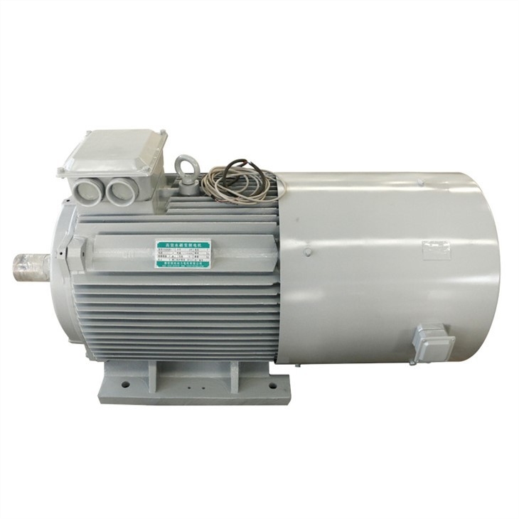
For variable-resource systems, define which controller owns maximum-power tracking or process regulation. For fixed-speed or isolated systems, define speed-governor behavior and how electrical load steps affect mechanical speed. For grid export, specify the grid-side inverter, synchronization, current control, reactive capability, anti-islanding, and interconnection requirements. The how a PMG works guide gives additional machine-level context for teams aligning mechanical and electrical responsibilities.
Check voltage under temperature and load
Winding resistance rises with temperature, changing internal voltage drop and copper loss. Semiconductor drops, magnet properties, cooling performance, and converter limits also vary with temperature. Ask for voltage and current behavior across the specified ambient and operating range. State whether curves are calculated or tested and at what winding condition.
Test more than steady rated load. Include no load, minimum useful speed, common operating points, rated condition, load steps, start, stop, and load rejection. Record terminal AC, DC-link voltage, output voltage, current, frequency, temperatures, and control states. If output is rectified, specify measurement bandwidth and ripple calculation. A handheld average reading can miss peaks that matter to capacitors or connected electronics.
Design protection for a source that remains magnetized
A PMG produces voltage whenever it turns. Opening a contactor removes load but does not remove magnetic excitation. Define overspeed, overvoltage, overcurrent, short circuit, ground fault, loss of cooling, converter failure, sensor failure, and emergency shutdown responses. Confirm the generator's permissible short-circuit behavior and do not assume a protective device can interrupt every possible DC fault without a suitable rating.
Coordinate isolation and discharge. Label points that may remain energized from rotation, DC capacitors, batteries, or the grid. Provide safe means to stop or restrain the prime mover and verify voltage before work. Where a dump load or braking resistor is used, monitor its temperature and availability. A protection scheme is incomplete if the component that absorbs rejected energy is not supervised.
Write interface and acceptance documents together
Create an interface control document listing generator phase and connection, voltage and frequency ranges, insulation, grounding, rectifier, DC link, inverter, sensors, communications, cooling, and protection ownership. Include connector and cable drawings, allowable tolerances, and version-controlled parameter files. Resolve which supplier guarantees each measurement point and which conditions are excluded.

The acceptance plan should identify factory and site tests, instruments, stabilization, load bank or simulated source, step sizes, tolerances, and raw-data format. Verify protective actions as well as regulation. A stable output during one steady test does not demonstrate load rejection, start-up, low-speed behavior, or a failed sensor. The three-phase PMG guide provides complementary phase and commissioning questions.
Send a voltage-regulation RFQ that can be answered
Provide the prime-mover speed range and dynamics; continuous and peak power; required AC, DC, battery, or grid interface; voltage band and ripple; load profile and steps; converter preferences or constraints; environment and cooling; cable and grounding; standards; and acceptance tests. Ask the supplier to return curves for generator terminal voltage and the regulated output, with assumptions and control boundaries clearly separated.
ENNENG's archived sources support ENNENG-CAND-007 for a permanent-magnet generator product activity and ENNENG-CAND-010 for a stated customization service. They do not prove that any voltage-speed-power combination can be supplied or that raw PMG output is inherently regulated. Review the permanent magnet generator page, then send the full electrical interface for a project-specific proposal.
Evidence boundary
The NREL publications linked above provide general synchronous-generator and power-electronics context for defined wind-system studies. They do not certify an ENNENG configuration or replace the applicable interconnection and safety standards. Company-source candidate records establish only product and customization context. Final voltage regulation, protection, and compatibility must be demonstrated for the exact generator, converter, prime mover, load, and operating range.