Permanent magnet generator factory acceptance test appears as a single line on an illustrative purchase schedule. The generator engineer draws a box around it. “What does that line buy?” she asks. Four answers arrive. One person expects a no-load spin; another expects full load. Procurement wants documents, while quality wants a witnessed inspection. Each is reasonable. None describes the same scope, so a clean matrix replaces the lonely schedule line.
First draw the border around the test object
The production identifier and drawing revision go in the top-left corner. The identity block grows around those two entries. It picks up winding and rotor, bearings and cooler, sensor and terminal details, then assembly status. Behind it is the approved map of power, speed, and voltage. Direction, duty, overspeed, environment, and shaft connection are written on that map rather than left in email.
Then the electrical engineer draws a dashed line. The generator terminals sit to the left of the dashed line. Rectifier and DC link may sit to the right, followed by inverter, transformer, filters, controls, dump load, brake, and protection. The order must say where that line stops. Which auxiliaries are inside the efficiency calculation? Nobody can compare results until that border is fixed.
The PMG voltage regulation guide helps with the split. There is no wound rotor field here for a conventional AVR to turn up or down. The voltage story instead runs through speed and load, winding impedance and temperature, then any rectification or conversion.
One requirement, one piece of evidence
A ruler moves down the specification. Every promised item receives an evidence route in the next column. Some end at a drawing or dimension. Others need an electrical check, a run at no load, a loaded point, a calculation, a component record, or work at site. Some rows need more than one.
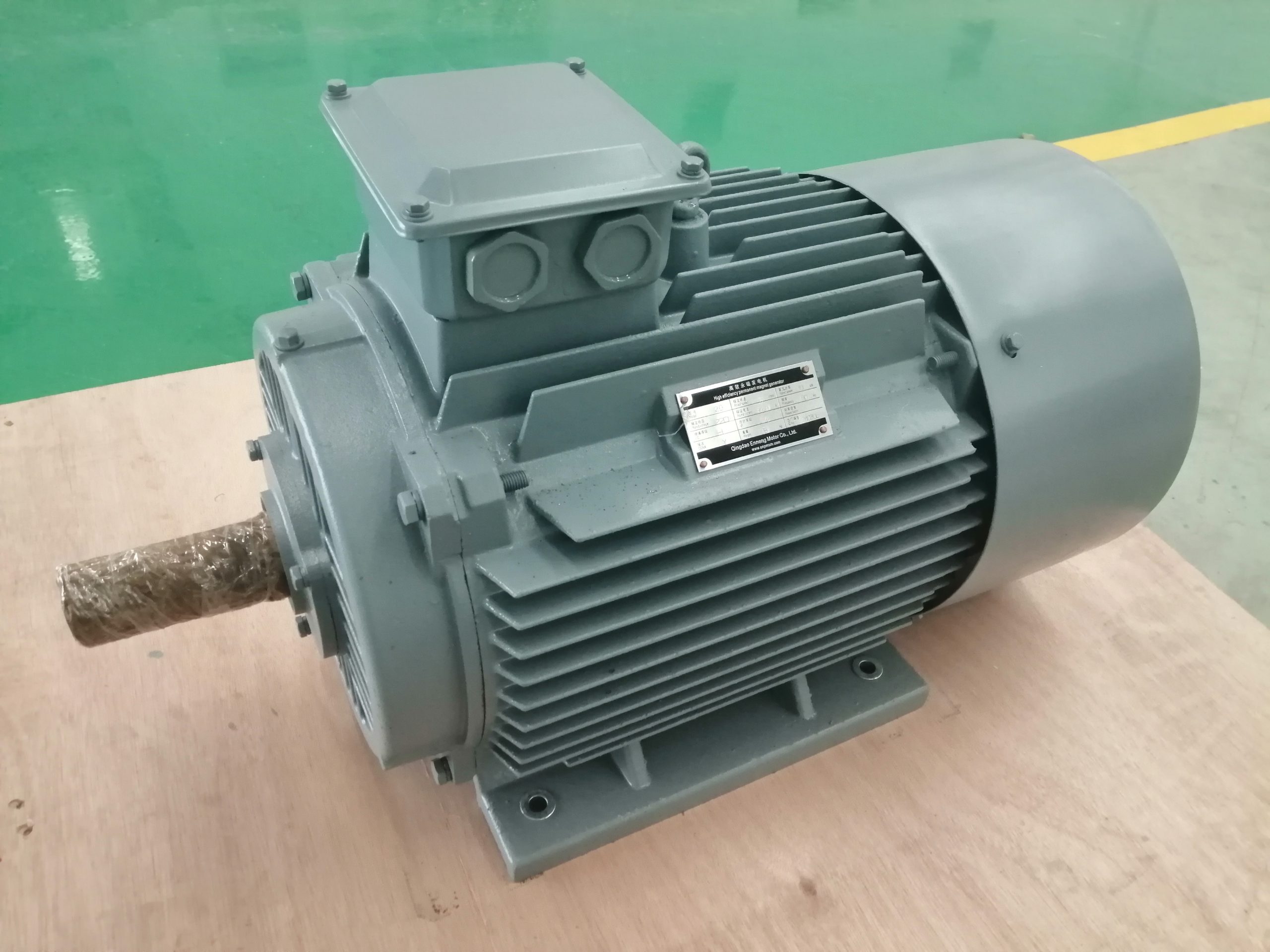
A proper row also carries a procedure revision, witness or hold point, instrument, condition, tolerance, report, and signatory. It sounds administrative until a result lands exactly on a limit. Then those details decide whether the number means anything.
The factory may not reproduce the prime mover, torque ripple, every speed, final converter, long cable, grid, or site cooling. Fine. The unavailable condition is assigned before the order to calculation, another subsystem test, or commissioning. It does not vanish.
The shaft file moves onto the same table
The load path is drawn from shaft through coupling or integrated interface, into bearings, housing, and base. At each junction the reviewer stops. Diameter? Pilot and bolts? Centerline, key or spline, runout? The remaining notes cover orientation, external loads, thrust, lubricant, seals, lifting, mass, and room for service.
An integrated direct-drive sketch refuses to stay inside one supplier's box. Shaft and air gap cross it; support stiffness, cooling, assembly order, and field access cross it too. The interface drawing and responsibility matrix need to agree before production.
Rotor build or balance records may be required, depending on the unit and order. The buyer names the record instead of asking for “all quality documents.” Revision, unit identity, acceptance, and any approved deviation travel together.
First electrical results: useful, but limited
The first results arrive from resistance and phase checks. Insulation and ground continuity follow. Sensors, heaters, and accessories are exercised, giving the team enough confidence to continue. They don't show rated power. They don't show efficiency either.
Test value, correction temperature, limit, and isolation method are recorded. Shared terminals make the isolation sketch essential. Electronics, surge parts, and sensors are kept away from the test voltage in the manner already agreed, before a cable is moved in haste.
The standards column points to IEC 60034-1:2026 for a current rating and performance framework where the machine falls inside its scope. The purchase order still needs to name the applicable requirements, edition, duty, and any industry-specific additions. “IEC compliant” is too wide to be a test instruction.
No-load voltage gets a map, not one dot
The first run climbs through the agreed speeds. Terminal voltage and frequency are noted at each stop, together with phase behavior and winding temperature. Instrument setup stays on the page, as does the condition of any rectifier or converter. Rotation and phase sequence are checked early.
No load does not mean no hazard. The magnet field is already there, so rotation creates voltage. Safe speed, isolation, discharge, access, and sequence are settled while the shaft is still stationary.
The finished curve answers a narrow question: what happened at no load under these recorded conditions? It cannot prove loaded voltage, thermal behavior, torque, converter response, or efficiency. The team writes that limitation under the graph so it cannot be lost later.
Loaded points need two meters and one clear boundary
Each required point has speed, mechanical torque or power, electrical output, time, voltage or DC-link target, temperature, and load condition. Normal duty is there. So are meaningful partial-load points and the corner most likely to drive heat or control limits.
Efficiency is simple arithmetic only after the boundaries become difficult. Is mechanical input measured from torque and speed? Does electrical output stop at the generator, DC link, or regulated AC? Are cooler pumps or fans counted? What uncertainty follows the instruments and calculation?
For efficiency and loss methods, the engineer checks IEC 60034-2-1:2024. A large machine that cannot be run at full load may lead the review to IEC 60034-2-2:2024, whose additional methods include a PM synchronous machine loss-summation annex. The project engineer selects the applicable method. A standard number on the cover cannot do that job alone.
The converter test is a sequence of events
When power electronics cross the order boundary, the test record keeps their identity and settings. Ratings and DC limits come first; switching, filter, cable, ground, communications, sensor scaling, and control mode follow.
The group then tells short fault stories. Load disappears. The shaft keeps driving. Where does the energy go? Speed rises. Which device sees it first? Cooling is lost. Does the controller warn, reduce power, or stop? A sensor fails. May the system restart?
Some events can be demonstrated at reduced energy. Others are safer as logic checks, simulations, secondary injection, calculations, or component evidence. The matrix says which. Every protection row still needs a detector, setting, delay, action, reset, and owner.
A vibration number needs its surroundings
A small cross on the drawing marks each accelerometer. In the margin are the support and mount, coupling state, speed, direction, and bandwidth. Those notes allow the factory number to meet a later site number on fair terms.
The vibration row may refer to IEC 60034-14:2018. Its factory procedures and limits apply to certain uncoupled machines within a stated scope, which the reviewer checks rather than assumes. The team checks whether the generator and setup fit that scope. An integrated machine or a unit outside the stated range may need a project method.
Factory readings still make a useful baseline. After shipping, alignment, coupling, and loading, the site can return to the same named points. A change then means more than two unrelated numbers in different reports.
The thermal run should be boring
Nothing dramatic should happen. The operating point holds. Cooling stays stable. Temperatures approach the agreed condition while the instruments keep recording.
The thermal sheet begins with the air or coolant entering the machine. Beside it are flow and pressure, auxiliary status, elapsed time, the rule for calling conditions stable, sensor points, and limits. Air cooling brings inlet and discharge readings. A liquid loop brings chemistry, temperature, pressure drop, exchanger, fittings, and the response to a leak.
One settled point is still one point. If full thermal testing is unavailable, the evidence may combine calculation, component data, selected load runs, and site verification. The report says so plainly. Alarm and trip signals are also followed through to the controller; a displayed temperature without an agreed action is incomplete protection.
A clean report keeps the messy history
The closing report can be reconstructed by someone who was absent. It identifies the unit and procedure revision, test setup and conditions, instruments and calibration, raw readings, calculations, uncertainty where relevant, limits, decisions, witnesses, and signatures. Photographs are added when they explain the setup or condition.
An early failure is not deleted after a successful retest. The corrective work, changed condition, and both results remain. Deviations get owners and signed dispositions. Keeping that untidy history makes the clean final result believable.
The release pack then gathers the data sheet, interfaces, terminal plan, sensor and protection schedules, converter file, manuals, spares, preservation, packing, and site sequence. Before the crate closes, someone checks the protected shaft, sealed openings, moisture control, lifting marks, and storage note.
The site closes what the factory could not
At site, the missing pieces finally share one place: foundation, alignment, coupling, prime mover, cooler, cables, conversion, load, controls, and emergency stop. Static checks come first. Rotation follows cautiously; speed and load arrive in planned steps.
A signed factory report does not remove open-circuit voltage or stored DC energy. The installed isolation, discharge, and access rules are tried before normal operation. Its first vibration, voltage, current, temperature, cooling, and protection records become the maintenance baseline.
ENNENG-CAND-007 admits only that archived pmacdrive.com material contained a permanent magnet generator product page. ENNENG-CAND-010 admits a limited historical customization statement. Neither proves a current rating, test capability, certificate, delivery, or fit. Buyers can review the PMG product context and send the mechanical input, electrical output, and witness points.
Evidence boundary
IEC publications supply general rating, efficiency, and vibration frameworks within their stated scopes. They don't certify an ENNENG generator. The admitted company records support only the historical statements above. Acceptance rests on the current order, approved drawings, selected standards, signed test matrix, actual readings, closed deviations, and final site interfaces.