Specify mechanical input and electrical output together
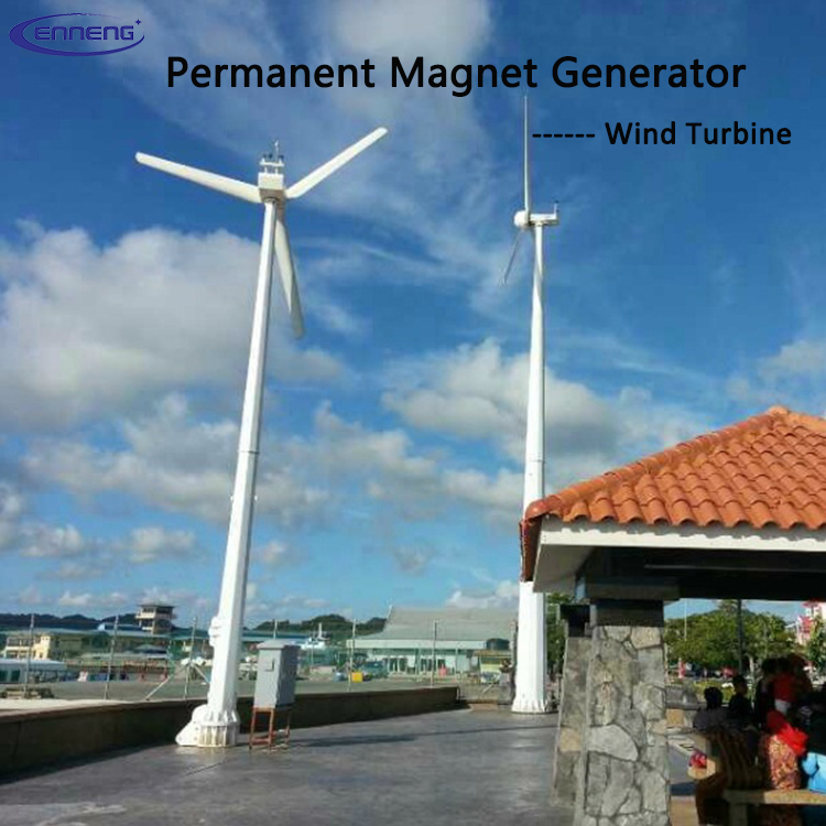
A permanent magnet generator inquiry needs both sides of the energy conversion boundary. On the mechanical side, define shaft speed range, continuous and transient torque, direction, overspeed, inertia and the prime mover. On the electrical side, define rated power, voltage, phase arrangement, frequency requirement, load type, rectification, converter and grid or storage interface. A power value without speed does not establish torque, and a voltage value without speed and winding context does not establish a generator design.
Describe the complete operating envelope rather than one rated point. Wind, hydro and engine-driven systems may spend substantial time away from nominal speed. The electrical interface may regulate voltage or DC-link conditions while mechanical input varies. These control responsibilities should be identified early so the generator, converter and supervisory control are designed as a coordinated system.
How a PMSG generates electrical power
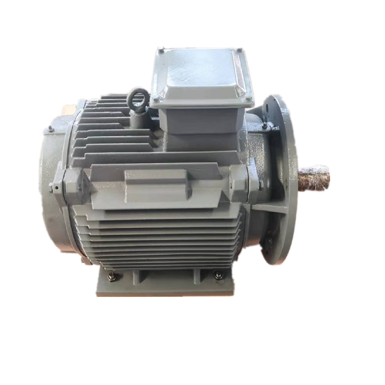
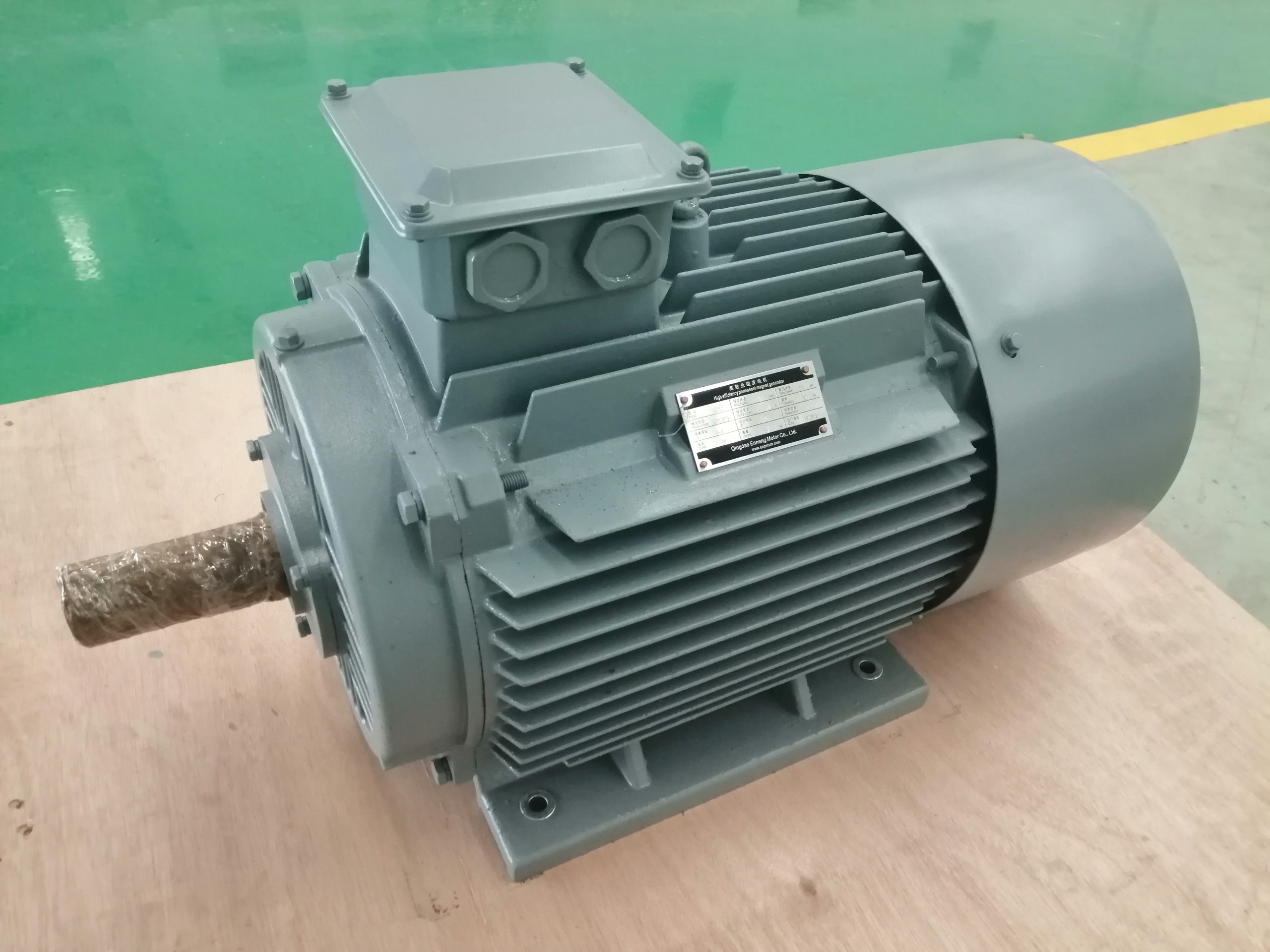
A permanent magnet synchronous generator uses rotor magnets to establish magnetic flux. Rotation changes the flux linkage of the stator windings and induces an alternating voltage. Electrical frequency is related to mechanical speed and pole count. Terminal behavior then depends on winding design, load, internal impedance, temperature and the connected power electronics. The principle is simple, while the usable system envelope requires electromagnetic, thermal and mechanical design.
Permanent magnets remove the need for a separate rotor field winding and its excitation system, but magnet material and rotor construction introduce their own design constraints. Demagnetization margin, short-circuit behavior, overspeed retention and thermal conditions need review. Do not infer these limits from a generic PMG definition. They belong in the project-specific technical data and verification plan.
Speed, voltage and frequency are linked
For a synchronous machine, electrical frequency follows rotational speed and pole count. If a project requires fixed grid frequency while the prime mover operates over a variable speed range, power electronics usually decouple generator frequency from grid frequency. NREL describes full-converter wind turbine models in which the converter handles the generator output and controls the grid interface. The converter architecture is therefore a core selection input, not an accessory chosen at the end.
State whether the desired output is variable-frequency AC, regulated AC, rectified DC or a DC link feeding an inverter. Include voltage range, current, power factor or DC-load behavior and fault expectations. For battery charging or isolated loads, describe the downstream regulation and protection. This prevents a winding optimized for one interface from being proposed for a different electrical system.