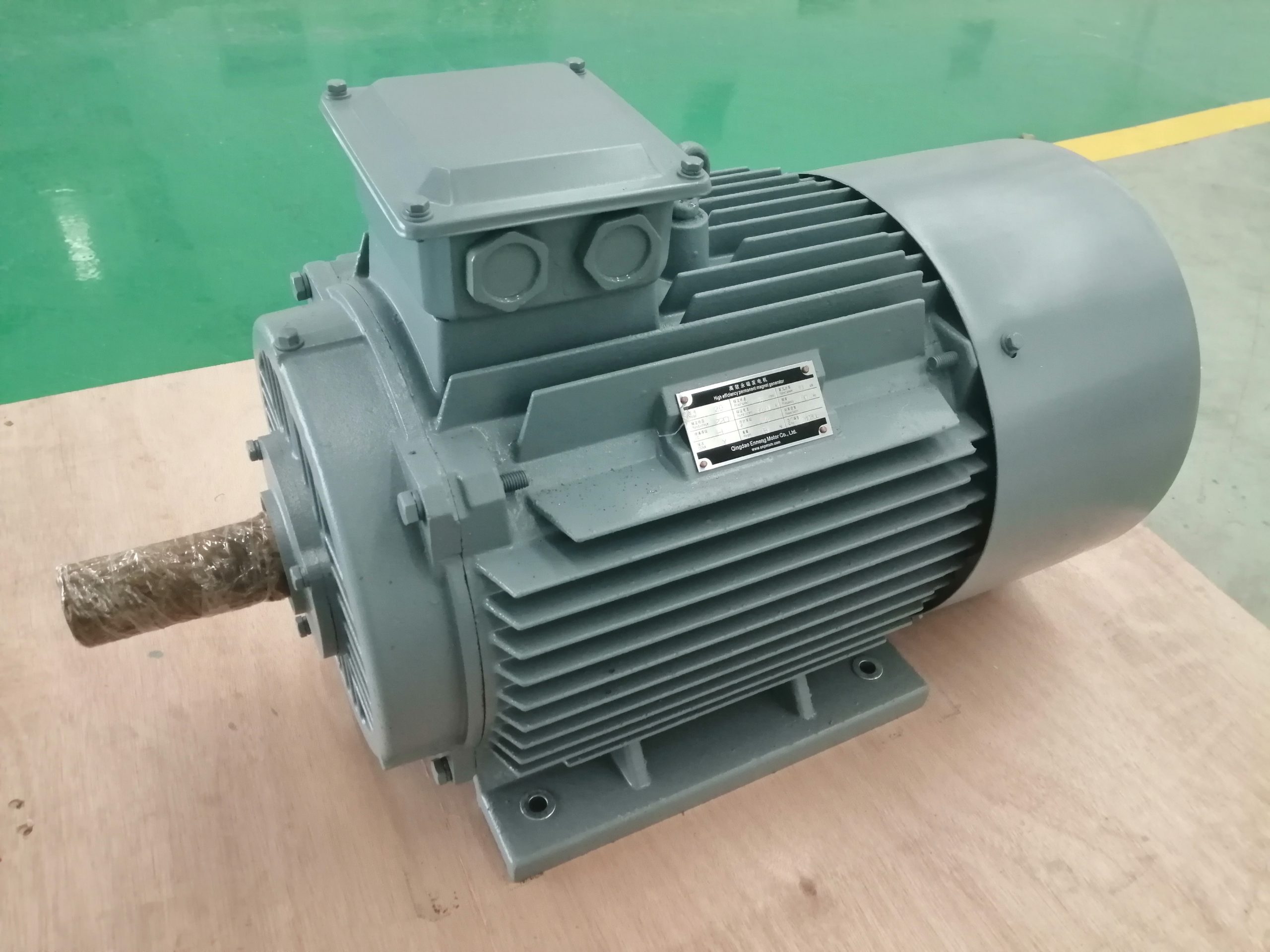
A permanent magnet generator for small hydropower should be selected from the turbine's measured speed and torque envelope, the site's head and flow variation, and the required electrical output. The word "small" does not define a generator. A low-head, high-flow turbine may turn slowly and require substantial shaft torque, while another site may use a speed increaser and a much faster machine. Begin with the water resource and turbine design, then specify the generator and power electronics as one system.
ENNENG's archived permanent magnet generator product route identifies low-head hydro as an application and describes configurable speed, voltage, cooling and mechanical arrangements. That establishes a product discussion, not a universal fit or a guaranteed performance level. The generator selection guide shows the data needed before any project-specific configuration can be assessed.
Start with the turbine, not the generator catalog
Head and flow shape the turbine choice and the shaft behavior it can deliver. The U.S. Department of Energy explains that turbine type is selected from the available head and flow; the hydraulic arrangement determines how water energy reaches the runner. A generator offer that starts with a rated kilowatt figure but omits the runner curve is missing the primary mechanical input. Ask the turbine designer for speed and torque at minimum, normal and maximum useful flow, plus the expected operating hours at each point.
Net head matters more than a single gross-head number. Intake, channel and penstock losses change the energy available at the turbine, and seasonal flow can move the operating point. Keep the underlying hydraulic assumptions in the project file. A generator supplier can match a machine to the supplied shaft duty, but it cannot infer the full hydrology from an electrical nameplate. If the turbine is already installed, measured shaft speed and electrical output under known water conditions are more useful than an unverified design target.
The U.S. Department of Energy's turbine guidance is a useful starting point for this boundary. It does not choose an ENNENG generator; it explains why head and flow must precede equipment comparison.

Build a speed-torque envelope for the hydro generator
Electrical power is the result of mechanical power after generator and downstream losses. On the shaft, mechanical power equals torque multiplied by angular speed. That relationship is especially important for direct-coupled low-speed equipment: when speed falls, a given power target calls for higher torque. The shaft, rotor, bearings, support structure and coupling all feel that torque. It would be misleading to describe a generator as "low speed" without stating the continuous torque at the actual speed.
Separate operating points from events. Record the continuous range during normal flow, the minimum useful speed, startup behavior, short overloads, runaway or overspeed cases, and shutdown sequence. A low-flow day may create a long thermal duty with little cooling air movement. A sudden electrical load rejection may let a turbine accelerate until mechanical controls or protection act. These are different design cases and should not be hidden under one rated rpm.
For an existing plant, collect the present generator's speed, output, temperature, vibration and bearing condition over representative water conditions. That baseline supports a fair retrofit comparison. Do not infer an energy gain from an old nameplate alone. The comparison must hold the water input and system boundary constant.
Decide how variable-speed output reaches the load
A permanent magnet synchronous generator produces an AC frequency linked to shaft speed and pole count. In variable-speed hydro, that means raw generator frequency is not automatically the fixed frequency required by a local AC load or grid. A rectifier and inverter, or another suitable converter arrangement, may provide the needed electrical interface. The converter must be specified for the whole generator voltage and current range, including abnormal operating cases.
The U.S. Department of Energy's Hydropower Vision report discusses variable-speed permanent magnet generators in small, low-head projects. Its system-level point matters here: speed flexibility is useful only when the turbine, generator and power conversion architecture are coordinated. It is not evidence that every hydro site will gain the same efficiency or that a generator can connect directly to an arbitrary grid.
Define whether the output will feed an isolated load, a battery/DC bus or a utility connection. Identify who supplies the rectifier, inverter, controls, protective relays, braking or dump-load path, and grid-compliance documentation. A project that asks only for "three-phase output" leaves too many decisions open. The three-phase generator and converter guide explains the electrical questions in more detail.
Check cooling, enclosure and water exposure separately
The archived ENNENG product page discusses air- and water-cooled configurations, horizontal and vertical installation, and alternative shaft arrangements. Those are possible design directions, not a promise that every combination is available or appropriate. Cooling choice depends on loss at the real duty points, ambient temperature, ventilation, contamination and access for maintenance. A low-speed unit enclosed near water can have a very different thermal problem from a well-ventilated machine in a dry equipment room.
Water exposure is a project condition, not an image label. Specify whether the generator is in a dry powerhouse, a splash-prone enclosure or an integrated submerged assembly. Give expected humidity, condensation, spray, flood level and cleaning practices. Protection and corrosion treatment must then be checked against the actual mounting and cable-entry design. Do not copy a legacy IP claim into a quotation without verifying the exact enclosure and test evidence.
Where a water-cooling circuit is proposed, define water quality, inlet temperature, flow, filtration, leak detection and ownership of pumps or heat exchangers. For air cooling, describe intake air quality, filters, ducting and loss of ventilation. Every option has auxiliaries and maintenance tasks; those belong in the system comparison.
Define the mechanical interface before ordering
A generator mounted horizontally next to a turbine has different support and thrust-bearing questions from a vertical assembly. The turbine designer and generator supplier need to agree on shaft position, coupling, axial and radial loads, bearing responsibility, alignment method and foundation stiffness. A drawing should show installation clearances and the route for cable terminals, sensors and cooling connections. If a speed increaser remains, include its losses and service requirements in the comparison.
Direct coupling removes one mechanical component but does not eliminate integration work. Rotor inertia changes the acceleration and shutdown response. Torque ripple and torsional behavior may affect the turbine shaft and coupling. A generator with acceptable electrical output can still be unsuitable if the turbine-side bearing or support arrangement is unresolved. List these interfaces explicitly in the request for quotation.
The U.S. Department of Energy describes a variable-speed permanent-magnet hydro prototype developed for a range of low-head conditions. It is a research example of a coordinated turbine-generator system, not a performance claim for this site or any ENNENG unit.
Prepare an RFQ that can be answered technically
Send net-head and flow information with the turbine model or curve. Add minimum, normal and maximum shaft speed; corresponding continuous torque; anticipated transients; operating hours by condition; and any overspeed limit. State the required AC or DC output, converter topology, voltage range, connection standard, and who owns the electrical protection. Include site temperature, water exposure, cooling utilities, mounting drawings, shaft loads and dimensional limits. Mark unknown values rather than estimating them as facts.
Ask the supplier to identify the selected operating points, assumptions and exclusions in its response. It should state the generator losses or efficiency basis, thermal boundary, mechanical interface and proposed verification method. For a retrofit, request a comparison at the same hydraulic input and delivered electrical boundary. A difference in generator-only efficiency is not automatically the difference in net plant output.
Before purchase, agree on factory and site acceptance criteria. Define which instruments will measure shaft and electrical quantities, where measurements will be taken, the stabilization period, and the pass criteria at the agreed duty points. Site acceptance also needs controls and protection checks. The technical inquiry form can begin with the known data; a complete engineering offer still requires the project drawings and agreed test boundary.
Questions that prevent expensive rework
Is a permanent magnet generator always preferable for small hydro? No. The choice depends on hydraulic variation, shaft speed, converter requirements, mechanical arrangement, service access and total installed cost. A conventional architecture may be appropriate at some sites. Compare complete systems under the same flow and output conditions.
Can raw generator AC be connected to a fixed-frequency load? Only if the electrical characteristics and control arrangement meet that load's requirements across operation. A variable-speed generator usually needs an appropriate power-electronic interface when a fixed-frequency output is required. The interface must also manage faults and load rejection.
Does a low-head site automatically need a low-rpm generator? No. Turbine design and any transmission determine generator speed. Low head and high flow often motivate large, slower runners, but the actual speed-torque curve settles the requirement. Specify the shaft data before choosing the generator family.
Technical references
The engineering discussion uses the U.S. Department of Energy turbine overview, its Hydropower Vision chapter, and the Penn State system example. ENNENG product and application scope were checked against archived first-party records; project-specific capability remains subject to engineering review.
Bring the operating data into one discussion.
Send the known duty points, electrical interface and mechanical drawings. Unknowns can be marked for follow-up.