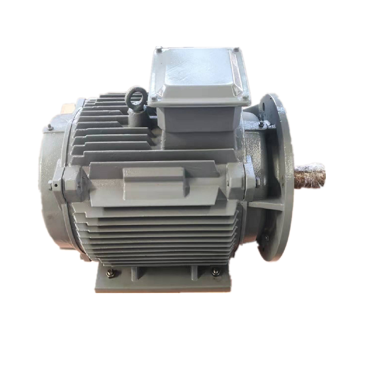
The whiteboard for permanent magnet generator load matching has two colors. Blue begins at the turbine shaft and stops at the generator. Red begins at the final electrical load and works backward through an inverter, DC link and rectifier. At first, the two lines do not meet.
That gap is where weak specifications live. A buyer may know the desired electrical power but not the prime mover’s speed-torque curve. A turbine supplier may know rpm and mechanical power but nothing about the converter window. The generator manufacturer can guess at the missing interface, but a guess is not a design input.
An illustrative review team keeps drawing until the blue and red lines touch. Along the way, every arrow gets a quantity, a condition and an owner.
The energy path fits on one sheet
The sketch begins wherever mechanical energy is born. On one project that might be a turbine runner; on another, an engine flywheel. A coupling leads to the PMG. Beyond its terminals the drawing changes character: diodes, a DC bus and an inverter appear before the cable finally reaches a useful load.
Someone draws a dashed box around the generator. Speed and torque sit on its left edge; voltage and current sit on the right. Cooling and control power remain outside the box. Now a terminal measurement cannot wander across the dashed line and reappear as “system output.” The PMG voltage regulation guide helps keep winding behavior apart from downstream regulation.
One member points at the phrase “generator efficiency” in an old quotation. At which boundary? The question stays beside the drawing until the answer is explicit: AC terminals, rectified DC or regulated output. Without that note, two apparently similar offers can describe different machines and different losses.
The prime mover tells a story, not one rpm
A hydro curve arrives with head and flow changing through the year. A wind rotor has a broad operating range. An engine holds speed more tightly but may bring torsional and load-acceptance questions. None of these sources is represented well by one nominal point.
The blue pencil pauses three times: where rotation first becomes useful, where the machine normally lives and where it must never linger. Torque is written beside those speeds. A brief surge gets a stopwatch symbol; the normal point gets hours. The slowest point looks harmless until the engineer calculates its torque. Suddenly shaft, bearings and frame deserve another look.
Mechanical power available at the coupling stays on its own row. Desired electrical delivery sits several rows lower, after the losses and auxiliaries that separate them. One best efficiency number is refused permission to represent a year. The group uses a small handful of real operating points instead, weighted by the time the prime mover is likely to spend there.
The load behaves badly on purpose
The red line starts with the most awkward load event. A battery nears its upper voltage. An isolated motor starts. The grid disappears. A heater is switched in at once. These moments reveal more than a neat rated-power box.
A battery engineer writes two voltage values and then circles the higher one. The controls engineer adds the charge limit. On an isolated AC project, the awkward event is different: a motor starts while another load remains connected. For a grid project, the inverter is named before anybody uses the phrase “grid output.” Variable-frequency terminals do not become fixed-frequency power by wording alone.
Load rejection gets the thickest red circle. Magnets do not wait for a field command; a turning rotor continues to generate. The team acts out the next few seconds. The converter reacts, the prime mover slows—or fails to—and another device may have to absorb energy. A dump resistor, turbine gate or blade command might enter the story. The safe answer belongs to the system, not to a solitary PMG checkbox.
The winding must satisfy two uncomfortable corners
The low-speed corner asks whether the converter can wake up and work. The high-speed corner asks a less friendly question: what voltage appears when the electrical load becomes small? A winding optimized only around the middle can fail either conversation.
So the proposal receives a few pinned points, each with speed and load. One column is open-circuit terminal voltage. Another is the loaded value. Regulated output sits farther to the right, after rectifier, cable and converter have taken their share. The columns are neighbors, not synonyms.
Frequency follows shaft speed and pole count in the synchronous machine. Where the delivered load needs fixed frequency over variable speed, power conversion becomes part of the core architecture. The three-phase PMG and converter guide gives that interface a more detailed check.
Heat appears between the map lines
Current and loss change across the operating map. The team places temperature notes beside speed and output, not in a separate generic box. A short electrical peak may be acceptable; a long low-speed point with weak cooling may not be.
The site is sketched beside the duty: a warm enclosure, thin air at altitude, spray or dust near the frame. Natural air keeps the drawing short. A blower adds a power wire and an interlock. Water adds pipework, trapped air, fluid condition and the uncomfortable question of what happens when flow stops.
If the purchase decision depends on efficiency, the group names the method and measurement boundary. IEC 60034-2-1:2024 sets out machine loss and efficiency methods within its scope, including synchronous machines. It does not include a converter merely because a quotation places both on the same page.
Mechanics refuse to stay mechanical
The shaft drawing arrives late and immediately changes the discussion. A flange fits, but the coupling leaves no tool space. A belt load acts farther from the bearing than one sketch implied. Arrows now show thrust and radial force at the places where they actually enter the shaft. The bearing boundary becomes visible.
Overspeed ignores the neat split between mechanical and electrical teams. Rotor stress rises on one side of the dashed box; voltage rises on the other. Before asking the factory to demonstrate anything, the group defines the credible speed, how long it might last and what event could create it. Testing may cover one safe point. Analysis and protection must carry the rest.
Long shafts, reciprocating engines or fast electrical torque changes can introduce torsional work that a basic generator RFQ misses. The project file either includes that review or explains why it is not needed. Silence is not the same conclusion.
Protection becomes a conversation between boxes
The team walks through a lost-grid event. The converter detects it first. Who tells the prime mover? What absorbs energy while the mechanical input falls? How is overspeed detected independently? The answers become arrows rather than a list of unrelated relays.
The same walk is repeated for overvoltage, overcurrent, temperature, vibration, cooling loss and emergency stop. Each condition gains a sensor, threshold owner, alarm or trip, mechanical action and restart rule. A temperature device with no control action is marked as unfinished.
Fault-current assumptions are left to project-specific machine data and the system study. Permanent magnet excitation cannot be switched off like a field winding. Generic protection values are therefore not copied from another generator.
The supplier returns a map, not a slogan
A useful proposal resembles the whiteboard after it has been cleaned up. Mechanical points on the left align with terminal readings on the right. Short events are visibly short. Cooling condition and converter window are printed beneath the map, where they cannot be mistaken for optional footnotes. Estimates look different from guarantees.
The first offer wins at nominal speed. The second spends more of the real duty inside a comfortable converter window. Once cooler, sensors, test work, documents and commissioning are added, the buyer has a system comparison rather than a beauty contest between rated points. The PMG products overview frames the discussion; it cannot do this matching work for the project.
Unknowns remain visible. Perhaps the turbine curve is preliminary or the cable run is not fixed. The supplier can condition the offer on those items and explain what changes when better data arrives.
Factory evidence meets site reality
At the factory, identity, drawings, resistance, insulation, phase and sensor checks come first. No-load voltage may be recorded across agreed speeds. Load, thermal, vibration and protection work follows only where the setup and purchased plan allow it. The PMG factory acceptance guide gives the witness file a structure.
For general rating and performance language, the team checks IEC 60034-1 where its scope fits. The purchase plan still names test conditions, instruments, tolerances and reports.
Site work closes the interfaces that the factory could not reproduce: the actual prime mover, alignment, final cooling, cables, converter, grid or isolated load, plant controls and load rejection. The first stable readings become the owner’s baseline.
The two colors finally meet
The finished sheet is not beautiful. It has arrows, revisions and a few blanks with names beside them. But the blue mechanical path now reaches the red electrical path without a hidden assumption.
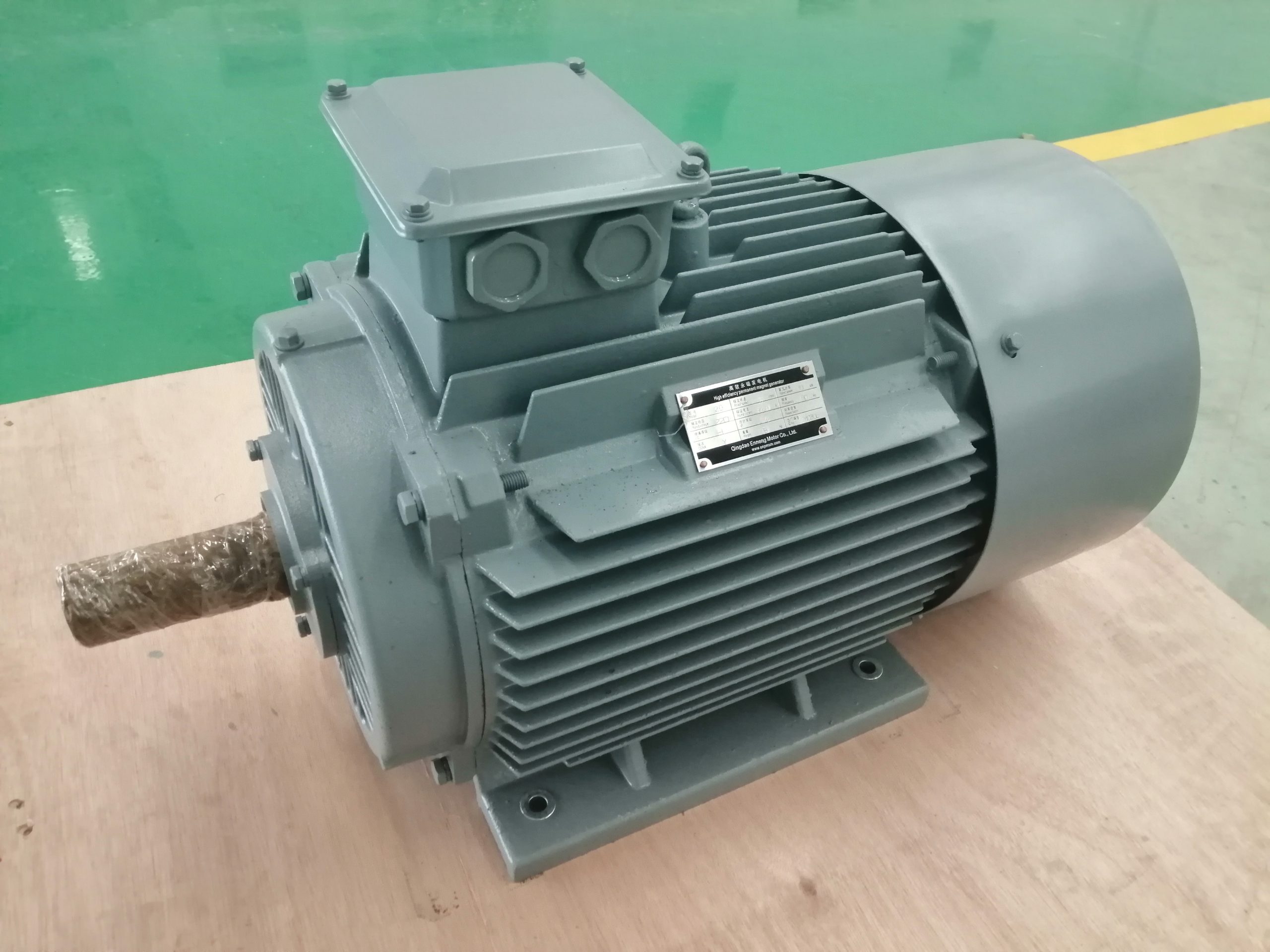
Archived ENNENG material supports historical PMG product and customization context only. It does not prove a current power range, service life, efficiency, IP rating, certification or delivery time. Those points belong to the current controlled offer and agreed evidence. Buyers can send the speed-torque map and electrical interface to begin that review.